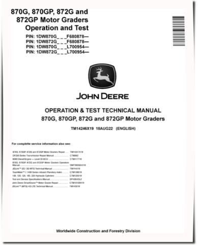
John Deere 870G, 870GP, 872G and 872GP Motor Graders (SN. from F680878, L700954) Operation and Test Manual (TM14246X19)
Specifications
-
Type Of DocumentOperation and Test Manual
-
Emission StandardsFinal Tier 4, Stage IV, Stage V
-
Type of equipmentMotor Grader
-
Serial Number680878-, 700954-
-
Model870G, 870GP, 872G, 872GP
-
Graders Serial Number680878-, 700954-
-
Graders PIN1DW870G_ _ _ F680878-, 1DW870G_ _ _ L700954-, 1DW872G_ _ _ F680878-, 1DW872G_ _ _ L700954-
Details
Table of Contents:
Introduction
Foreword
Manual Identification - READ THIS FIRST!
General Information
Safety
Diagnostics
Transmission Control Unit (TCU) Diagnostic Trouble Codes
Engine Control Unit (ECU) Diagnostic Trouble Codes
Primary Display Unit (PDU) Diagnostic Trouble Codes
Vehicle Control Unit (VCU) Diagnostic Trouble Codes
Hydraulic Valve Controller (HVC) Diagnostic Trouble Codes
Auxiliary Valve Controller (AVC) Diagnostic Trouble Codes
Switch Module 1 (SM1) Diagnostic Trouble Codes
Six-Wheel Drive (6WD) Diagnostic Trouble Codes
Cab Video Display (VC1) Diagnostic Trouble Codes
Gear Selector Module (GSM) Diagnostic Trouble Codes
Left Pod Joystick Control (LJ3) Diagnostic Trouble Codes
Right Electrohydraulic (EH) Dual Joystick Control (JR1) Diagnostic Trouble Codes
Left Electrohydraulic (EH) Dual Joystick Control (JL1) Diagnostic Trouble Codes
Operational Checkout Procedure
Operational Checkout Procedure
Engine
Theory of Operation
System Diagrams
Diagnostic Information
Adjustments
Tests
Electrical System
Theory of Operation
System Diagrams
Electrical Component Diagnostic Information
Diagnostic Information
Monitor Operation
Diagnostic Test Box
Adjustments
Tests
Six-Wheel Drive (6WD)
Theory of Operation
System Diagrams
Diagnostic Information
Adjustments
Tests
Power Train
Theory of Operation
System Diagrams
Diagnostic Information
Tests
Hydraulic System
Theory of Operation
System Diagrams
Diagnostic Information
Tests
Heating and Air Conditioning
Theory of Operation
System Diagrams
Diagnostic Information
Tests
APPENDIX
Section 9000
Section 9001
Section 9005
Section 9010
Section 9015
Section 9016
Section 9020
Section 9025
Section 9031


